Note
Access to this page requires authorization. You can try signing in or changing directories.
Access to this page requires authorization. You can try changing directories.
This article helps you connect your virtual network to your virtual hub using the Azure portal. You can also use PowerShell to complete this task. Repeat these steps for each VNet that you want to connect.
Before you create a connection, be aware of the following:
- A virtual network can only be connected to one virtual hub at a time.
- In order to connect it to a virtual hub, the remote virtual network can't have a gateway (ExpressRoute or VPN) or RouteServer.
- To create a cross-tenant virtual network connection to the virtual hub, refer to Connect cross-tenant virtual networks to a Virtual WAN hub
Important
- If VPN gateways are present in the virtual hub, this operation as well as any other write operation on the connected VNet can cause disconnection to Point-to-site clients as well as reconnection of site-to-site tunnels and BGP sessions.
Add a connection
In the Azure portal, go to your Virtual WAN In the left pane, select Virtual network connections.
On the Virtual network connections page, select + Add connection.
On the Add connection page, configure the connection settings. For information about routing settings, see About routing.
- Connection name: Name your connection.
- Hubs: Select the hub you want to associate with this connection.
- Subscription: Verify the subscription.
- Resource group: Select the resource group that contains the virtual network to which you want to connect.
- Virtual network: Select the virtual network you want to connect to this hub. The virtual network you select can't have an already existing virtual network gateway.
- Propagate to none: This is set to No by default. Changing the switch to Yes makes the configuration options for Propagate to Route Tables and Propagate to labels unavailable for configuration.
- Associate Route Table: From the dropdown, you can select a route table that you want to associate.
- Propagate to labels: Labels are a logical group of route tables. For this setting, select from the dropdown.
- Static routes: Configure static routes, if necessary. Configure static routes for Network Virtual Appliances (if applicable). Virtual WAN supports a single next hop IP for static route in a virtual network connection. For example, if you have a separate virtual appliance for ingress and egress traffic flows, it would be best to have the virtual appliances in separate VNets and attach the VNets to the virtual hub.
- Bypass Next Hop IP for workloads within this VNet: This setting lets you deploy NVAs and other workloads into the same VNet without forcing all the traffic through the NVA. This setting can only be configured when you're configuring a new connection. If you want to use this setting for a connection you've already created, delete the connection, then add a new connection.
- Propagate static route: This setting lets you propagate static routes defined in the Static routes section to route tables specified in Propagate to Route Tables. Additionally, routes will be propagated to route tables that have labels specified as Propagate to labels. These routes can be propagated inter-hub, except for the default route 0/0.
Once you've completed the settings you want to configure, select Create to create the connection.
Note
- To delete a virtual network connected to the virtual hub, you must delete both the virtual network connection and virtual network resource.
Understanding Bypass Next Hop IP for workloads within this VNet
Virtual Network connections to Virtual WAN hubs have a configurable property named VNetLocalRouteOverrideCriteria (Bypass Next Hop IP for workloads within this VNet in Azure Portal).
This property defines how traffic is routed to workloads deployed in a Virtual WAN spoke VNET when a static route is configured on the Virtual WAN spoke Virtual Network connection and the Virtual Network address space is a subnet within the static route.
- Disabled (default): All traffic matching static route ranges gets redirected through the next hop, even within the spoke VNet itself
- Enabled: Traffic to IPs within the spoke's address space bypasses static routes and goes directly to target, while other traffic follows configured routing
You can enable this feature via the following steps:
- Portal: Set Bypass Next Hop IP for workloads within this VNet to Yes when creating VNet connection (default is No)
- API/CLI/PowerShell: Set
vnetLocalRouteOverrideCriteria = "equals"(default is"contains")
Note
This feature can only be configured during the creation of a VNet connection. To enable it on an existing connection, you must delete and recreate the VNet connection.
Design Scenario
You’ve set up a Virtual WAN Hub connected to two spokes:
- NVA Spoke: Contains a load balancer (10.2.0.1) that routes traffic between two NVA virtual machine instances (10.2.0.2 and 10.2.0.3). This spoke is also directly peered to another VNet (the indirect spoke) containing a VM with IP 10.2.1.1.
- Direct Spoke: Another VNet connected directly to the Virtual WAN Hub. This VNet contains a VM with IP 10.0.0.1.
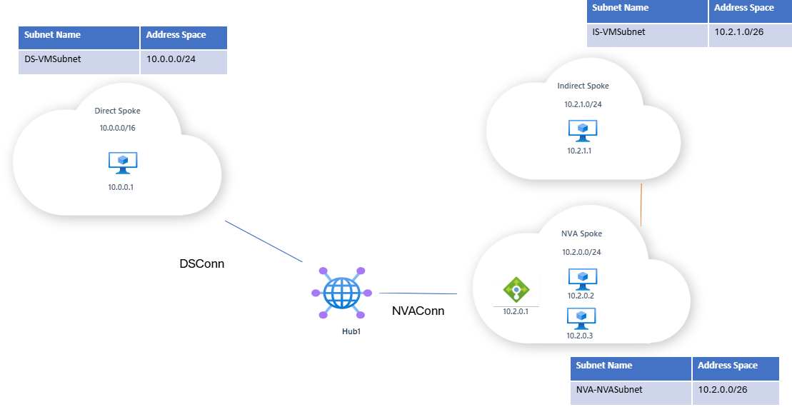
A static route is configured on NVAConn to ensure that any traffic destined for the NVA spoke or the indirect spoke is routed through the load balancer at IP 10.2.0.1.

Traffic behavior with VNetLocalRouteOverrideCriteria disabled
If Bypass Next Hop IP for workloads within this VNet is disabled/vnetLocalRouteOverrideCriteria = contains, then:
- Traffic from the direct spoke to a VM in the NVA spoke (e.g., 10.2.0.2) will be redirected by the static route to the load balancer (10.2.0.1). This may result in routing to an unintended VM instance (e.g., traffic intended for 10.2.0.3 is routed to 10.2.0.2 instead; path may vary based on load balancer hashing).
- Intended traffic flow: blue line
- Actual traffic flow: red line
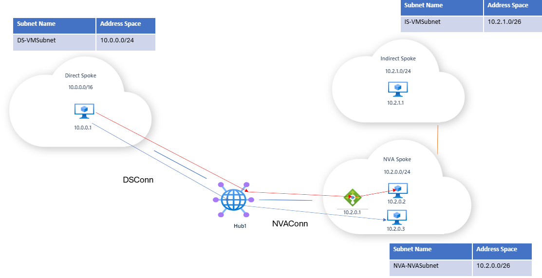
- Traffic within the broader static route will also be routed to the load balancer. For example, traffic from the direct spoke VM (10.0.0.1) to the indirect spoke VM (10.2.1.1) will also be routed through the load balancer due to the static route.

Traffic Behavior With Bypass Next Hop IP Enabled
If Bypass Next Hop IP for workloads within this VNet is enabled/vnetLocalRouteOverrideCriteria = equals:
- Traffic destined for an address within the NVA spoke’s prefix bypasses the static route and goes directly to the target VM (e.g., 10.2.0.3).
- Traffic flow: blue line from 10.0.0.1 to 10.2.0.3
- Traffic targeting an address outside the NVA spoke’s prefix (but still within the static route’s range), such as 10.2.1.1 in the indirect spoke, continues to follow the static route and is sent to the load balancer.
- Traffic flow: red line from 10.0.0.1 to 10.2.1.1 (path may vary based on load balancer hashing)

Next steps
For more information about Virtual WAN, see the Virtual WAN FAQ.